- 您现在的位置:买卖IC网 > Sheet目录319 > COP8SG-EPU (National Semiconductor)BOARD PROTOTYPE/TARGET COP8
�� �
�
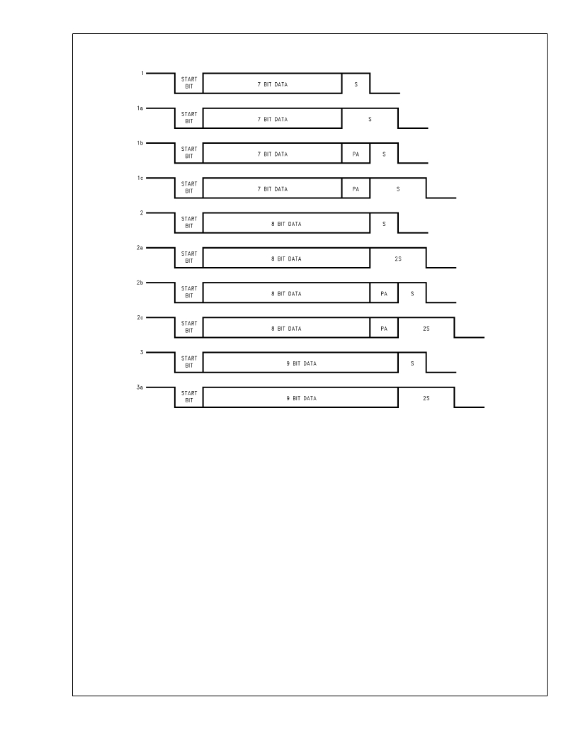
�USART� Operation�
�(Continued)�
�FIGURE� 13.� Framing� Formats�
�DS012829-15�
�USART� INTERRUPTS�
�The� USART� is� capable� of� generating� interrupts.� Interrupts�
�are� generated� on� Receive� Buffer� Full� and� Transmit� Buffer�
�Empty.� Both� interrupts� have� individual� interrupt� vectors.� Two�
�bytes� of� program� memory� space� are� reserved� for� each� inter-�
�rupt� vector.� The� two� vectors� are� located� at� addresses� 0xEC�
�to� 0xEF� Hex� in� the� program� memory� space.� The� interrupts�
�can� be� individually� enabled� or� disabled� using� Enable� Trans-�
�mit� Interrupt� (ETI)� and� Enable� Receive� Interrupt� (ERI)� bits� in�
�the� ENUI� register.�
�The� interrupt� from� the� Transmitter� is� set� pending,� and� re-�
�mains� pending,� as� long� as� both� the� TBMT� and� ETI� bits� are�
�set.� To� remove� this� interrupt,� software� must� either� clear� the�
�ETI� bit� or� write� to� the� TBUF� register� (thus� clearing� the� TBMT�
�bit).�
�The� interrupt� from� the� receiver� is� set� pending,� and� remains�
�pending,� as� long� as� both� the� RBFL� and� ERI� bits� are� set.� To�
�remove� this� interrupt,� software� must� either� clear� the� ERI� bit�
�or� read� from� the� RBUF� register� (thus� clearing� the� RBFL� bit).�
�Baud� Clock� Generation�
�The� clock� inputs� to� the� transmitter� and� receiver� sections� of�
�the� USART� can� be� individually� selected� to� come� either� from�
�an� external� source� at� the� CKX� pin� (port� L,� pin� L1)� or� from� a�
�source� selected� in� the� PSR� and� BAUD� registers.� Internally,�
�www.national.com�
�28�
�the� basic� baud� clock� is� created� from� the� oscillator� frequency�
�through� a� two-stage� divider� chain� consisting� of� a� 1–16� (in-�
�crements� of� 0.5)� prescaler� and� an� 11-bit� binary� counter.� (Fig-�
�ure� 14).� The� divide� factors� are� specified� through� two� read/�
�write� registers� shown� in� Figure� 15.� Note� that� the� 11-bit� Baud�
�Rate� Divisor� spills� over� into� the� Prescaler� Select� Register�
�(PSR).� PSR� is� cleared� upon� reset.�
�As� shown� in� Table� 6,� a� Prescaler� Factor� of� 0� corresponds� to�
�NO� CLOCK.� This� condition� is� the� USART� power� down� mode�
�where� the� USART� clock� is� turned� off� for� power� saving� pur-�
�pose.� The� user� must� also� turn� the� USART� clock� off� when� a�
�different� baud� rate� is� chosen.�
�The� correspondences� between� the� 5-bit� Prescaler� Select�
�and� Prescaler� factors� are� shown� in� Table� 6.� There� are� many�
�ways� to� calculate� the� two� divisor� factors,� but� one� particularly�
�effective� method� would� be� to� achieve� a� 1.8432� MHz� fre-�
�quency� coming� out� of� the� first� stage.� The� 1.8432� MHz� pres-�
�caler� output� is� then� used� to� drive� the� software� programmable�
�baud� rate� counter� to� create� a� 16x� clock� for� the� following� baud�
�rates:� 110,� 134.5,� 150,� 300,� 600,� 1200,� 1800,� 2400,� 3600,�
�4800,� 7200,� 9600,� 19200� and� 38400� (Table� 1).� Other� baud�
�rates� may� be� created� by� using� appropriate� divisors.� The� 16x�
�clock� is� then� divided� by� 16� to� provide� the� rate� for� the� serial�
�shift� registers� of� the� transmitter� and� receiver.�
�发布紧急采购,3分钟左右您将得到回复。
相关PDF资料
CORE1553-DEV-KIT
KIT DEVELOPMENT FOR IP CORE1553
CP131-AG
LNR PWR SUP 5V 8A, +/-12V 1.7A
CPC1590P
MOSFET GATE DVR ISO 8-FLATPACK
CPC5002G
ISOLAT DGTL 3.75KVRMS 2CH 8-DIP
CPCI-D-3U-300C
PWR SUPLY DC/DC CPCI 300W 3UX8HP
CPD250-4530G
PWR SUP 250W 3.3/5/12/-12V QUAD
CS4161YN8
IC DRIVER H-BRDG DUAL 85MA 8DIP
CS5461A-ISZ
IC ENERGY METERING 1PHASE 24SSOP
相关代理商/技术参数
COP8SGR728M7
功能描述:8位微控制器 -MCU RoHS:否 制造商:Silicon Labs 核心:8051 处理器系列:C8051F39x 数据总线宽度:8 bit 最大时钟频率:50 MHz 程序存储器大小:16 KB 数据 RAM 大小:1 KB 片上 ADC:Yes 工作电源电压:1.8 V to 3.6 V 工作温度范围:- 40 C to + 105 C 封装 / 箱体:QFN-20 安装风格:SMD/SMT
COP8SGR728M7/NOPB
功能描述:8位微控制器 -MCU RoHS:否 制造商:Silicon Labs 核心:8051 处理器系列:C8051F39x 数据总线宽度:8 bit 最大时钟频率:50 MHz 程序存储器大小:16 KB 数据 RAM 大小:1 KB 片上 ADC:Yes 工作电源电压:1.8 V to 3.6 V 工作温度范围:- 40 C to + 105 C 封装 / 箱体:QFN-20 安装风格:SMD/SMT
COP8SGR728M8
功能描述:8位微控制器 -MCU RoHS:否 制造商:Silicon Labs 核心:8051 处理器系列:C8051F39x 数据总线宽度:8 bit 最大时钟频率:50 MHz 程序存储器大小:16 KB 数据 RAM 大小:1 KB 片上 ADC:Yes 工作电源电压:1.8 V to 3.6 V 工作温度范围:- 40 C to + 105 C 封装 / 箱体:QFN-20 安装风格:SMD/SMT
COP8SGR728M8/NOPB
功能描述:8位微控制器 -MCU RoHS:否 制造商:Silicon Labs 核心:8051 处理器系列:C8051F39x 数据总线宽度:8 bit 最大时钟频率:50 MHz 程序存储器大小:16 KB 数据 RAM 大小:1 KB 片上 ADC:Yes 工作电源电压:1.8 V to 3.6 V 工作温度范围:- 40 C to + 105 C 封装 / 箱体:QFN-20 安装风格:SMD/SMT
COP8SGR728N8
功能描述:8位微控制器 -MCU RoHS:否 制造商:Silicon Labs 核心:8051 处理器系列:C8051F39x 数据总线宽度:8 bit 最大时钟频率:50 MHz 程序存储器大小:16 KB 数据 RAM 大小:1 KB 片上 ADC:Yes 工作电源电压:1.8 V to 3.6 V 工作温度范围:- 40 C to + 105 C 封装 / 箱体:QFN-20 安装风格:SMD/SMT
COP8SGR728N8/NOPB
功能描述:8位微控制器 -MCU RoHS:否 制造商:Silicon Labs 核心:8051 处理器系列:C8051F39x 数据总线宽度:8 bit 最大时钟频率:50 MHz 程序存储器大小:16 KB 数据 RAM 大小:1 KB 片上 ADC:Yes 工作电源电压:1.8 V to 3.6 V 工作温度范围:- 40 C to + 105 C 封装 / 箱体:QFN-20 安装风格:SMD/SMT
COP8SGR740N8
功能描述:IC MCU 8BIT CMOS OTP 40DIP RoHS:否 类别:集成电路 (IC) >> 嵌入式 - 微控制器, 系列:COP8™ 8SG 其它有关文件:STM32F101T8 View All Specifications 特色产品:STM32 32-bit Cortex MCUs 标准包装:490 系列:STM32 F1 核心处理器:ARM? Cortex?-M3 芯体尺寸:32-位 速度:36MHz 连通性:I²C,IrDA,LIN,SPI,UART/USART 外围设备:DMA,PDR,POR,PVD,PWM,温度传感器,WDT 输入/输出数:26 程序存储器容量:64KB(64K x 8) 程序存储器类型:闪存 EEPROM 大小:- RAM 容量:10K x 8 电压 - 电源 (Vcc/Vdd):2 V ~ 3.6 V 数据转换器:A/D 10x12b 振荡器型:内部 工作温度:-40°C ~ 85°C 封装/外壳:36-VFQFN,36-VFQFPN 包装:托盘 配用:497-10030-ND - STARTER KIT FOR STM32497-8853-ND - BOARD DEMO STM32 UNIV USB-UUSCIKSDKSTM32-PL-ND - KIT IAR KICKSTART STM32 CORTEXM3497-8512-ND - KIT STARTER FOR STM32F10XE MCU497-8505-ND - KIT STARTER FOR STM32F10XE MCU497-8304-ND - KIT STM32 MOTOR DRIVER BLDC497-6438-ND - BOARD EVALUTION FOR STM32 512K497-6289-ND - KIT PERFORMANCE STICK FOR STM32MCBSTM32UME-ND - BOARD EVAL MCBSTM32 + ULINK-MEMCBSTM32U-ND - BOARD EVAL MCBSTM32 + ULINK2更多... 其它名称:497-9032STM32F101T8U6-ND
COP8SGR740N8/NOPB
制造商:Texas Instruments 功能描述: